Understanding Your Self-Cleaning Oven
Many ovens boast a self-cleaning feature, yet manual cleaning remains crucial for maintaining optimal performance and addressing specific issues. Experts suggest that self-cleaning cycles, while convenient, don’t always deliver perfect results, and sometimes require supplemental cleaning efforts.
The Self-Cleaning Cycle: How It Works
The self-cleaning cycle operates at extremely high temperatures, typically exceeding 880°F (470°C), to incinerate food residue within the oven. This intense heat transforms baked-on spills and grease into ash, which can then be easily wiped away once the cycle completes and the oven cools. However, this process isn’t without its caveats. The cycle locks the oven door for safety, preventing accidental opening during the high-heat phase.
It’s important to note that while effective, the self-cleaning function isn’t a substitute for regular maintenance. Consumer Reports testing reveals that even with self-cleaning capabilities, ovens still benefit from occasional manual attention to tackle particularly stubborn messes. The function was developed to simplify oven care, but isn’t always a complete solution, and can even be potentially dangerous if not used correctly.
Limitations of the Self-Cleaning Feature
Despite its convenience, the self-cleaning cycle has notable limitations. Experts and lab tests demonstrate it doesn’t always eliminate all baked-on food, requiring supplemental manual cleaning for truly spotless results. The high heat can also trigger unpleasant burning smells and, in some cases, even smoke, particularly with significant grease buildup. Furthermore, the intense temperatures can potentially damage oven components over time, though modern ovens are designed to withstand these cycles.
It’s crucial to understand that self-cleaning isn’t a magical fix; it’s a tool that requires responsible use. Some ovens may struggle with exceptionally tough messes, and the cycle’s effectiveness varies between models. Regular, lighter cleaning efforts can minimize the need for frequent, lengthy self-cleaning cycles, extending the oven’s lifespan and maintaining optimal performance.
When Manual Cleaning is Necessary
Manual cleaning becomes essential when self-clean cycles fail, produce excessive smoke, or when the oven door remains locked post-cycle, demanding immediate attention.
Self-Clean Cycle Failures
Despite the convenience, self-cleaning cycles aren’t foolproof and can sometimes fail to fully remove baked-on food and grease. Consumer Reports testing reveals that ovens vary significantly in self-clean performance, meaning some require more manual intervention than others. If a cycle leaves substantial residue, attempting another self-clean isn’t always the answer; it’s often more effective to switch to manual cleaning. This is particularly true for heavily soiled ovens or those with spills that have carbonized over time.
Furthermore, a malfunctioning heating element or control panel can cause a self-clean cycle to terminate prematurely, leaving the oven in a partially cleaned state. In these instances, manual cleaning is the only viable option to restore the oven to a usable condition. Ignoring these failures can lead to further buildup and potentially damage the oven’s components.
Burning Smells and Smoke During Self-Clean
The intense heat of a self-clean cycle often vaporizes food residue, producing noticeable smells and sometimes even smoke. While a slight odor is normal, excessive smoke signals a significant buildup of grease and food particles. This indicates the self-clean function is working too hard, and potentially isn’t effectively removing the debris. Continuing the cycle in this state can be dangerous and may not improve the cleaning outcome.
When encountering strong smells or smoke, immediately stop the self-clean cycle and allow the oven to cool completely. Manual cleaning becomes essential to remove the source of the smoke and prevent further issues. Thoroughly scrubbing the interior with appropriate cleaning products will address the accumulated residue that the self-clean cycle couldn’t handle.
Oven Won’t Unlock After Self-Clean
A common frustration is an oven door that refuses to unlock after completing a self-clean cycle. This safety feature prevents opening the extremely hot oven prematurely. However, if the door remains locked even after cooling, a malfunction may have occurred. Do not force the door open, as this could cause damage or injury.
Before attempting manual cleaning, ensure the oven has completely cooled – this can take several hours. If the door still won’t unlock, consult your oven’s manual for specific troubleshooting steps. If the issue persists, manual cleaning of the door seal and locking mechanism might be necessary. Carefully inspect for any obstructions or debris preventing the release. If unsuccessful, professional repair is recommended.

Gathering Your Cleaning Supplies
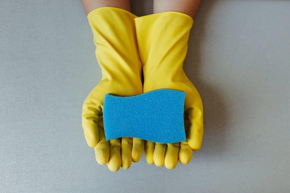
Essential supplies include baking soda, vinegar, dish soap, a spray bottle, scrub brushes, a sponge, rubber gloves, and protective eyewear for a thorough cleaning.
Essential Tools for Manual Cleaning
Successfully tackling a dirty oven manually requires assembling the right arsenal of tools. A sturdy scrub brush is paramount, capable of dislodging baked-on food without damaging the oven’s interior. Several brushes with varying bristle stiffness are ideal for different levels of grime.
Sponges, both abrasive and non-abrasive, are essential for wiping surfaces and applying cleaning solutions. Rubber gloves protect your hands from harsh chemicals and hot water. A spray bottle is crucial for evenly distributing cleaning mixtures. Old towels or rags are needed for wiping and absorbing loosened debris.
For stubborn spots, a plastic scraper can be incredibly helpful, avoiding scratches that metal tools might cause. A vacuum cleaner with a hose attachment is useful for removing loose particles before and after scrubbing. Finally, consider a flashlight to illuminate dark corners and ensure no areas are missed during the cleaning process.
Choosing the Right Cleaning Products
Selecting appropriate cleaning products is vital for effectively tackling oven grime while safeguarding the appliance and your health. A baking soda paste, created by mixing baking soda with water, is a gentle yet powerful natural cleaner, excellent for loosening baked-on food. Vinegar, especially white vinegar, cuts through grease and deodorizes the oven interior;
For tougher stains, commercially available oven cleaners can be used, but always prioritize those labeled as fume-free or low-odor. Ensure adequate ventilation when using chemical cleaners. Avoid abrasive cleaners that can scratch the oven’s surface.
Dish soap can be added to cleaning solutions for extra degreasing power. Lemon juice offers a natural alternative for cutting grease and leaving a fresh scent. Always test any cleaning product in an inconspicuous area first to ensure it doesn’t damage the oven’s finish.

Preparing the Oven for Manual Cleaning
Before starting, remove racks and accessories, protecting your kitchen floor with drop cloths or newspaper to catch drips and loosened debris during the process.
Removing Oven Racks and Accessories
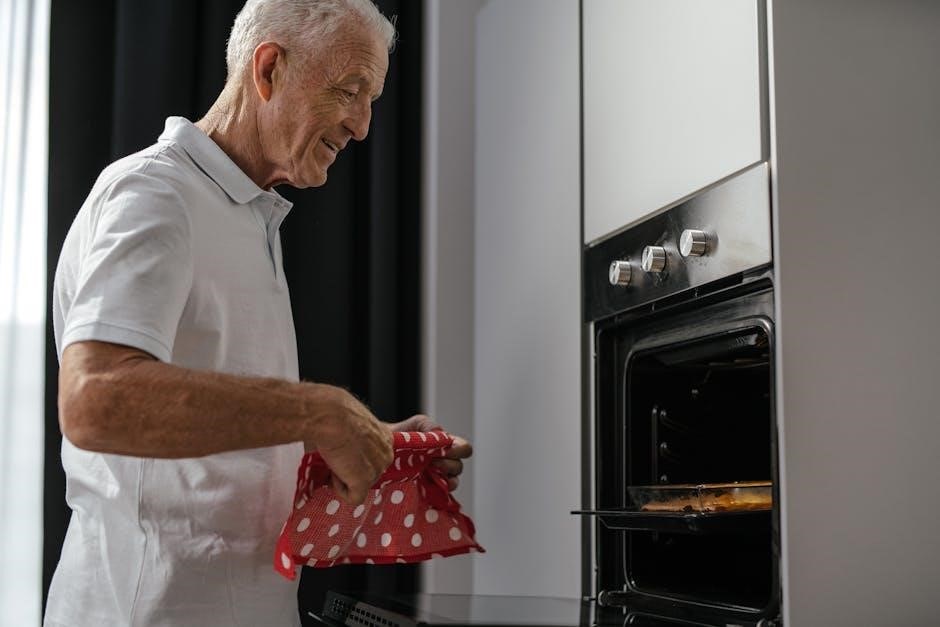
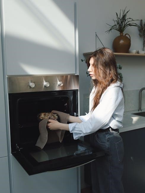
Begin the manual cleaning process by completely emptying the oven cavity. This crucial first step involves carefully removing all oven racks, baking stones, thermometers, and any other accessories stored inside. Removing these items provides unobstructed access to all interior surfaces, ensuring a thorough cleaning.
Oven racks often accumulate significant baked-on grease and food particles. These racks can be cleaned separately, either by soaking them in a solution of hot, soapy water or by scrubbing them with a dedicated oven rack cleaner. Consider cleaning the racks outdoors or in a well-ventilated area, especially if using strong cleaning agents.
Don’t overlook smaller accessories! Ensure everything removable is taken out before proceeding to protect them from cleaning solutions and to maximize your cleaning efficiency.
Protecting the Kitchen Floor
Before applying any cleaning solution, diligently protect your kitchen floor from drips and spills. Manual oven cleaning often involves using liquids and abrasive cleaners that can damage flooring materials. A simple yet effective method is to lay down several layers of old newspapers or a drop cloth around the base of the oven.
Plastic sheeting or old towels also provide excellent protection. Ensure the protective covering extends far enough to catch any splashes or runoff during the scrubbing and wiping phases. This preventative measure safeguards your floors from potential staining, etching, or discoloration.
Consider the type of flooring you have; some materials are more susceptible to damage than others. Prioritizing floor protection demonstrates care and prevents costly repairs or replacements.
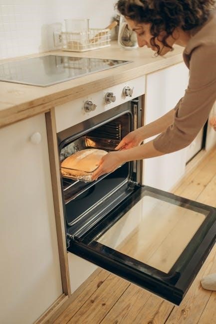
Step-by-Step Manual Cleaning Process
Begin by applying your chosen cleaning solution generously throughout the oven’s interior, focusing on heavily soiled areas. Allow sufficient dwell time for optimal results.
Applying the Cleaning Solution
Generously spray or spread your chosen cleaning solution across all interior surfaces of the oven, ensuring thorough coverage. Pay particular attention to baked-on food residue and greasy areas, as these require extended contact time with the cleaning agent. For stubborn spots, consider applying a thicker layer or utilizing a paste-like formula.
Allow the solution to dwell for the recommended period, typically ranging from 30 minutes to several hours, depending on the product and the severity of the grime. This dwell time allows the cleaning agents to penetrate and loosen the baked-on debris, making subsequent scrubbing more effective. Remember to ventilate the kitchen during this process, as some cleaning products may release fumes.
Avoid spraying directly onto heating elements or the oven’s pilot light, if applicable. A spray bottle is ideal for even distribution, but a sponge or cloth can also be used for targeted application. Consistent and complete coverage is key to a successful manual cleaning.
Scrubbing Baked-On Food and Grease
After the cleaning solution has dwelled, begin scrubbing the oven’s interior with a non-abrasive sponge, cloth, or nylon-bristled brush. Avoid using steel wool or harsh scouring pads, as these can damage the oven’s enamel coating. Apply firm, consistent pressure to loosen baked-on food and grease, working in circular motions.
For particularly stubborn areas, a plastic scraper can be helpful, but exercise caution to prevent scratching the surface. Reapply cleaning solution as needed to keep the surface lubricated and aid in the scrubbing process. Focus on areas like the bottom of the oven, around the heating elements (when cool), and any visible spills or splatters.
Persistence is key; heavily soiled ovens may require multiple scrubbing sessions. Remember to wear gloves to protect your hands from the cleaning solution and grime. A little elbow grease will yield significant results!
Wiping Down the Interior
Once you’ve thoroughly scrubbed the oven’s interior, it’s time to wipe away the loosened grime and cleaning solution. Dampen a clean microfiber cloth with warm water and begin wiping down all surfaces, starting from the top and working your way down. Rinse the cloth frequently in clean water to avoid spreading dirt around.
Pay close attention to corners, crevices, and areas around the heating elements. Multiple wipes may be necessary to remove all traces of the cleaning solution and residue. Inspect the oven carefully for any remaining stubborn spots and repeat the scrubbing process if needed before wiping again.
Ensure no cleaning solution remains, as it could potentially emit fumes during future oven use. A clean, residue-free interior is essential for safe and effective cooking.
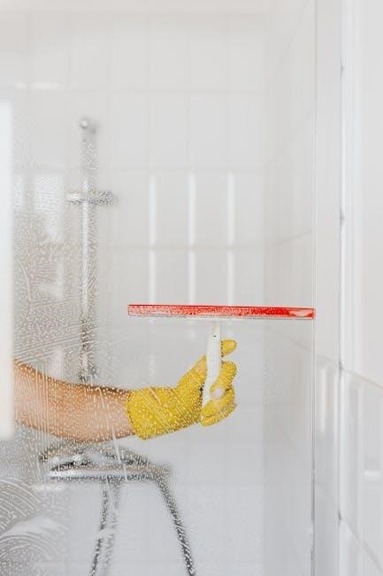
Cleaning the Oven Door
The oven door often accumulates stubborn stains and grease; dedicated attention is needed to restore its clarity and ensure a spotless appearance.
Addressing Stubborn Stains on the Glass
Baked-on food and grease can create particularly challenging stains on the oven door’s glass surface, requiring a targeted approach for effective removal. Begin by creating a paste of baking soda and water – a classic, gentle abrasive. Apply this paste liberally to the stained areas, ensuring complete coverage. Allow the paste to sit for at least 15-20 minutes, or even longer for exceptionally stubborn residue, to allow it to penetrate and loosen the grime.
After the soaking period, use a non-abrasive sponge or cloth to gently scrub the glass. Avoid harsh scouring pads, as these can scratch the surface. For particularly difficult spots, consider adding a few drops of dish soap to the baking soda paste for enhanced cleaning power. Rinse thoroughly with clean water and wipe dry with a microfiber cloth to reveal a sparkling, stain-free oven door.
Cleaning the Door Gasket
The oven door gasket, or seal, is often overlooked but crucial for maintaining oven temperature and preventing leaks. It’s a magnet for food particles and grease, requiring regular cleaning to ensure a tight seal. Begin by gently peeling back the gasket to access trapped debris. A damp cloth with a mild dish soap solution is usually sufficient for routine cleaning; avoid harsh chemicals that could damage the rubber.
For stubborn grime, create a paste of baking soda and water and apply it to the gasket, letting it sit for a few minutes before gently scrubbing with a soft brush or cloth. Rinse thoroughly with clean water and ensure the gasket is completely dry before closing the oven door. A clean gasket contributes to efficient oven operation and prevents energy waste.
Final Touches and Prevention
Regular wiping after each use minimizes buildup, reducing the need for intensive cleaning. Protecting your investment through consistent care ensures a sparkling, efficient oven.
Rinsing and Drying the Oven
After thoroughly scrubbing and letting the cleaning solution sit, a comprehensive rinsing process is essential. Utilize clean, warm water and a fresh sponge or microfiber cloth to meticulously wipe down all interior surfaces, ensuring no cleaning residue remains. Multiple rinses may be necessary, particularly in areas where the cleaning solution was heavily applied or baked-on food was stubborn.
Pay close attention to corners, crevices, and the oven door, as residue can easily accumulate in these spots. Once you’re confident all traces of the cleaner are gone, proceed to drying. A clean, dry microfiber cloth is ideal for this step, as it won’t leave lint behind. Allow the oven to air dry completely before using it, ensuring no moisture lingers, which could cause issues during cooking. A final inspection guarantees a spotless and safe cooking environment.
Tips to Minimize Future Cleaning Needs
Proactive measures can significantly reduce the frequency and intensity of oven cleaning. Immediately addressing spills as they happen prevents them from baking onto the oven’s surfaces, making future cleaning much easier. Consider using oven liners to catch drips and crumbs, simplifying cleanup. Regularly wiping down the interior after each use, even a quick wipe, prevents buildup.
When baking, utilizing oven-safe dishes with lids or covering food can contain splatters. Avoid excessively greasy or sugary foods, as these are notorious for creating stubborn messes. If you do use the self-cleaning cycle, remember it doesn’t eliminate the need for occasional manual touch-ups. Consistent, small efforts are far more effective than infrequent, extensive cleaning sessions, preserving your oven’s condition and your valuable time.